Analytics

28 May, 2012

TUTORIAL: 3D Mesh Construction in Quartz Composer - Part 2


- Part 1


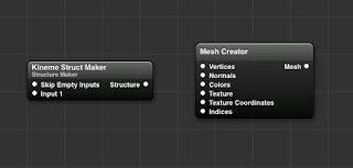
In the previous tutorial we used structures to construct a polygon mesh in the shape of a triangle. Now it’s time to add some colour to our vertices. This information needs to be presented to the Mesh Creator patch in much the same way as the vertex one. First though we will be converting our triangle to a square. In order to do this we will simply be adding one more vertex to our structure and changing the existing values to reflect the new shape. 

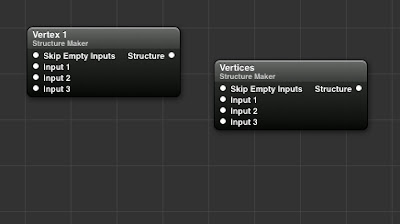
First change the number of inputs in the "Vertices" structure maker form 3 to 4, then we duplicate one of our existing vertex structures. When constructing a quad in OpenGl the vertex order is important, especially for later on when we will be adding texture coordinates. In this case it needs to begin from the Bottom Left Vertex, on to the Top Left, Bottom Right and ending on the Top Right.  

The unconventional running order is due to the fact that when we are still building a set of triangles (instead of an actual quad) using an OpenGL Triangle Strip. This means we have two triangles on top of each other, but using the triangle strip allows to do this with only 4 vertices instead of 6. For a more detailed explanation follow the liked article.

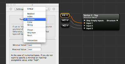
1 - Bottom Left: X = -0.5, Y = -0.5 , Z = 0

2 - Top Left: X = −0.5, Y = 0.5, Z = 0

3 - Bottom Right: X = 0.5, Y = -0.5, Z = 0

4 = Top Right: X = 0.5, Y = 0.5, Z = 0


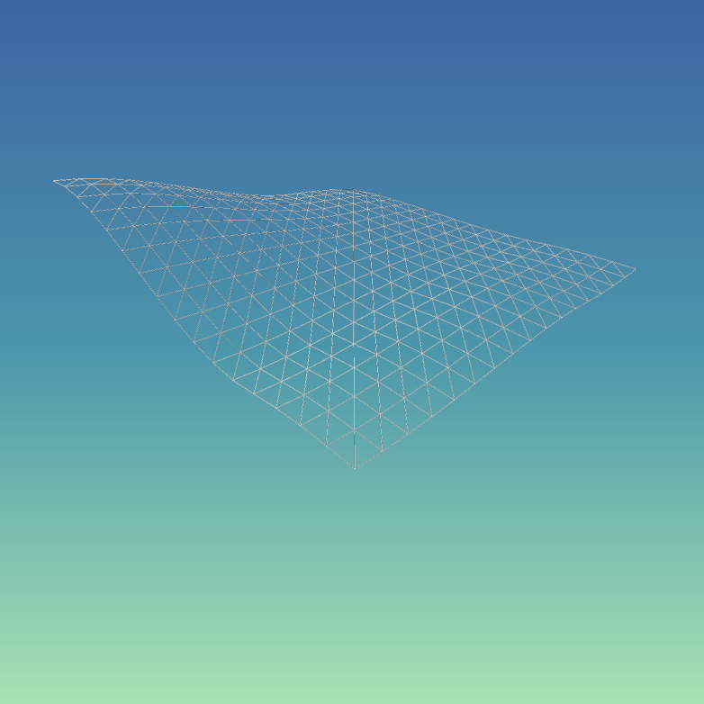
Our viewer now displays a square instead of a triangle. Since we will be adding new structures, it’s a good idea at this stage to clean up our workspace a bit. To do this we select all the patches related to the vertices and hit the “Create Macro” button at the top. Our patches are now neatly held in a small macro container that we rename “Vertices”. 


Next are the color structures. To begin, we duplicate out “Vertices” macro and rename it “Colors”. Since Color information requires four values (RGBA) we need to update our individual structure maker patches to have 4 inputs, and rename the input splitters as well


Now we could at this point enter each colour value manually, but that would be a pain. Instead we drag in a "Color To RGB" patch that allows us to choose a color from the color picker and output its individual RGBA values. 


With this done we can now choose 4 different colors and assign them to each vertex. To make it so that we don’t have to open the macro each time we want to try new colors, we can publish the colour input of each Color To RGB patch so that they appear outside the macro in the main view. Connect the Colors structure output to the input in the Mesh Creator patch and we now have a Quad with coloured vertices!


Next up are texture coordinates. You won’t be surprised to learn this will be yet another structure. We take our existing structure and change the input number to 2. The splitters will be named X and Y. Rather than the actual position values, X and Y will oscillate between 0 and 1:

1 - Bottom Left: X = 0, Y = 0 

2 - Top Left: X = 0, Y = 1

3 - Bottom Right: X = 1, Y = 0

4 = Top Right: X = 1, Y = 1


Our mesh is now ready to display image textures! To do this simply connect any image to the “Texture” input in the Mesh Creator Patch. Note that to display an image with its original colors you will have to set every vertex color to be white, otherwise the image displayed will be appear tinted!

Next up, actual 3-dimensional objects and Normals!

27 May, 2012

TUTORIAL: 3D Mesh Construction in Quartz Composer - Part 1


This tutorial will outline basic use of the Mesh Creator patch and the Mesh  Renderer patch in Quartz Composer, in addition to the Kineme Structure Maker patch.

The fundamental thing to understand about creating 3D meshes in QC is that the application in this regard is a basic front for common OpenGL functions. Therefore, to gain a basic understanding of how these things work we can first consult any tutorial on OpenGl basics, then find a way to apply it to QC. 
A good resource for this is the series of tutorials by NeHE productions .

We will create a basic polygon, and assign colour and texture coordinates to it so that we can change its appearance and display images on its surface.

To begin, we drag in the Mesh Creator patch. This patch is responsible for taking in all the data required to create a polygon and creating a mesh from it. The mesh will then be displayed by the Mesh Renderer patch.


A polygon is, at its most basic, a series of vertices. Each vertex is in turn a point in space, determined by its XYZ position. In order to create a polygon we will therefore need to first specify the XYZ  coordinates of a vertex, repeat the process for the amount of vertices required to determine the shape chosen, then feed this to the Mesh Creator and then to the Mesh Renderer.

What kind of input does the Mesh Renderer take? To determine this we hover with the mouse over the "Vertices" input slot, and see that the type is Structure.

We have dealt with structures in a previous tutorial . This time however we are not just reading a structure, we are creating one. To do this, we require and external patch by the good people at Kineme called Structure Maker. The patch is part of the “Kineme Data Tools” plugin set and is found here.


This patch will enable us to determine a series of inputs and make a structure out of them. To build our polygon we will begin by setting the vertex list. We rename the Structure Maker patch to “Vertices”.

For this tutorial we will create a triangle, so we will need a total of 3 vertices as inputs. In order to prepare the Structure Maker patch, we need to change the number of inputs from the default 1 to 3. We do this by selecting the “Parameters” panels for the patch, navigating to the “Settings” tab and changing the number to 3.


Now that the Vertices Structure Maker is ready, we need to create the individual vertices. As each vertex is determined by 3 values ( XYZ ) we will need to create a structure for each. As we already have a SM patch ready, we duplicate it and rename it to “Vertex 1 - Top”. This will contain the coordinates for the top vertex of the triangle. We also create input splitters for each vertex, remembering to change the input type from “Virtual” to “Number”.


The coordiantes for our "Top" vertex will be:  X = 0 , Y = 0.5 , Z = 0 . This will place the top vertex in the centre horizontally but above the centre vertically.

Now all that is left is to repeat the process by simply duplicating the setup for the other two vertices and changing the values to create a triangle shape:

  - TopX = 0 , Y = 0.5 , Z = 0
  - Bottom LeftX = −0.5 , Y = −0.5 ,  Z = 0
  - Bottom RightX = 0.5 , Y = -0.5 ,  Z = 0


We then simply connect the Mesh Creator output to the “Mesh” input of the Mesh Renderer patch… et voilĂ ! We have our very own triangle mesh created entirely in Quartz Composer. 


As you have probably noticed, there are a few more inputs in the Mesh Creator patch. We will be dealing with those in future parts of the tutorial. In the meantime feel free to play with the values of the vertices and perhaps move them around in space. 
Notice that even though we have obtained a 2D image of a triangle, the mesh is actually a 3D object able to move around in space, meaning we are not restricted to simple triangles but we can create potentially any shape. That triangle however is the foundation of all 3D models. I hope you have enjoyed this tutorial and make sure to keep an eye open for the next instalments.

Part 2


07 May, 2012

The Future Of Quartz Composer?


When I first started using Macs, around 3-4 years ago, I poked around the installation disk, and installed a set called Developer Tools. Looking around, I found an odd program called Quartz Composer. It wasn’t clear what the program did, all you could see was an empty workspace, and you were then supposed to drag in nodes and connect them, and then produce filters and screen savers. I had no idea how to use it, there were no guides or tutorials online, so I ignored it. 

Revisiting it later and after finding some scattered tutorials, something clicked and I realised the power of QC. Here was a programming tool, a real programming tool, that required no coding. Sure, it was supposed to be for screen savers and filters, but it was obviously capable, with some imagination, of so much more. 
(It might be of interest to note that I am primarily trained in drawing and illustration, so visual programming or coding was initially totally foreign to me, making my adoption of a tool like QC all the more relevant).

Even after finding ways to extend the functionality with plugins and at the same time finding a forum to discuss and ask questions (both thanks to the work of the people at Kineme.net) I still couldn’t help noticing that the world of QC development was very quiet. No guides, no books, no websites or youtube videos, most developers seemed to ignore the existence of QC. Apple too seemed to ignore it, barely providing a mailing list(!) as a way to discuss and seek help. When OS X Lion came out, QC still had a text file with the same release notes from the previous operating system. 

So let’s be honest: QC is a bit of a forgotten tool. It sees no love from Apple, and I fear they might pull the plug on it any moment now, and leave us users in the cold. Because the truth is, there is nothing quite like QC out there. 

Visual programming can (and should!) be fun, intuitive, and most of all require no (or minimal) coding skills. 
My fear is that in the near future QC might share the same fate of apps like iWeb (another tool I loved and depended on) and get pulled with no replacement in sight. 

QC is, as far as I am concerned, the ideal programming environment. Not just for graphics, because it could be extended to be so much more.
But I’m not sure that Apple realises what they have, or what a great learning tool QC could be with the right vision behind it. Wouldn’t connecting nodes be the ideal way to make at least small programs on something like the iPad? Wouldn’t it be a great way to teach the fundamentals of programming logic to kids? Evidently no one at Apple is thinking about this, or if they are they are being very quiet about it.

At this point in time, I cannot honestly recommend that you learn QC (at least not exclusively), because I don’t know how long it will be around for. QC is such a unique environment that nothing really matches its ease of use and intuitiveness. Most of what you learn in it will take you ages to transfer to a different programming environment, and even then it will take you 10 times longer than it ever did in QC. There seems to be no appreciation for node-based programming environments. Programming is meant to be a hardcore skill that requires you to learn and master several programming languages that require the inclusion of 3 libraries and countless lines of code just to display a coloured square in a window.

Even when using fairly simple languages like Lua or Python, getting to display anything on the screen requires you to find a code editor, some library or tool to display the code (languages don’t come with built-in ways to display graphics or sound), hope that it runs well or is updated to the latest specfication of the language and hope it is well documented. Then every time you write the code and make a change, you need to close the window and restart your app just to see any changes displayed. Every time. Imagine if you had to turn the lights of the room on and off again every time you changed a pencil drawing or a painting just to see the results. I don’t have to point out how much faster any of this would be in QC (not to mention in real-time).

I think it's a relevant criticism, as the workflow can be (apart from a huge barrier to newcomers), a big hindrance on creativity.

This creativity is very dear to me, because the rise of visual programming represents possibly the first time that a new generation possesses a tool that no artist of the previous generations (or even in the history of art) had at their disposal.
It's a brand new brush and a brand new canvas.  

The ideal tool would be something akin to QC, but where all the nodes and their source code can be inspected and changed in real time, inside the application. Some apps like Nodebox do this, but are restricted to 2d drawing and don’t seem to have the span of QC. The other thing about QC is that it is tightly integrated with the OS (although this has sometimes made it look like the only thing it is good for is filters or Screen Savers). 
Blender also relies heavily on a node-based environment for material generation and compositing, hopefully in the future one will be able to create and modify geometry as well. If Apple ever pulls QC, I think our hopes rest with the open source community.

While I haven’t really dedicated much time to QC lately, instead focusing on learning to code, I would still like to write some tutorials for QC like one I have planned on generating meshes and 3D objects. While it’s still around, I’ll keep on using it and loving it just as I have so far.


30 May, 2011

Quartz Composer Procedural Terrain Mesh Test

The terrain mesh is generated by creating vertex structures with iterators and feeding it to the Kineme GL Triangle Structure patch. I initially tried with the built in Mesh Creator patch, but this one seems faster and more stable. 

The current method is not incredibly fast as it uses individual quads rather than long triangle strips. A 64*64 grid takes 17 seconds! I have a version which is faster that uses iterated triangle strips, but I’m having some problems wrapping the end of the mesh so I need to clean it up further. A lot of the slow-down is due to the way I calculate vertex colors I think.

The height values are generated by a Noise patch and entirely mediated by math to get the “island” effect, with the terrain coming down at the edges into flat land. No heightfield images are used.
Normals are not yet calculated so no shadows for now. The vertex colors are generated through the Color Map patch fed by gradients and an initial colouring of the vertices from black to white based on the height value. 

Overall quite primitive and unpolished, but I look forward to refining it.


These are earlier versions using the built-in Mesh Creator patch. The slight advantage of this is that you can use the Grid Normals Generator patch to generate normals and get shadows, however this proved very unstable so I’ll probably have to find an alternative way.


13 May, 2011

TUTORIAL: Structures and Index Members in Quartz Composer


This tutorial will outline basic use of Structures and the Index Member patch in Quartz Composer.

A structure is simply a way of organising data. It can be thought of as a series of labeled folders containing files, like a folder with pictures of your summer vacation that contains subfolders organised by date.

Even though we might not notice it, in Quartz Composer we deal with structures in many ways: any time we load something from a folder, when we create groups of values dynamically with Iterators, when building a 3d mesh etc.
It’s probably easier to just show you, so in this tutorial we will outline a simple way of displaying RSS feeds in Quartz Composer.

We begin by loading a patch called RSS Importer.  As the name implies, this takes an internet RSS feed and downloads the contents much like any other reader does.


This patch receives as input the feed URL and an “update signal” boolean. It outputs the feed information and the articles, plus the download progress and a quick pulse signal when the download is done.

The output of this patch is where we start dealing with structures. Rather than giving us a huge block of text, the output will be structured the same way as when we read it on the website (title, date, content, author etc.). 
The article list will be a structure, and each article will itself be a structure made of the individual elements of the article.

In order to view the contents we need a way to display the text. We do this by loading the Image with String patch. This is an extremely useful patch that allows us to display text in Quartz Composer as an image. We can change the font, alignment, size etc. 
We drag in a Sprite patch to display the output of the Image with String patch.


As a test, we can try to connect the “Article List” output to the “String” input of the Image with String patch, and the “Image” output from there to the Sprite "Image" input. All we get is a pretty blurry <QCStructure> bit of text. 
This is because no actual text is loaded, and the Image with String is just passing the output type information. So the RSS patch is outputting a structure, and we need to separate the individual elements of the structure to pass it to the IWS (Image with String) patch. 


Before we do anything else, let’s clean up the image output of the patches so that it’s readable. We select the settings tab for the IWS patch, and change the dimensions from "Fixed" to "Dynamic". This will allow us to deal in pixels rather than units. 


Next we connect the “Display Width” and “Display Height” outputs from the IWS patch to the "Width" and "Height" inputs of the Sprite patch.


The text is now clearer but still small, so we change the “Font Size” input in the IWS patch to 20. The text is now big and readable.


We’re still seeing the old bit of text, so let’s get to the article data. As we said, the RSS importer outputs structures, and we need to separate the various elements in order to display them.
To separate the elements we make use of the Structure Index Member patch. 
This patch takes in a structure and only selects the member of the structure we need from the index.


We need to connect the Article List output from the RSS patch to the Structure input of the SIM (Structure Index Member) patch. We then connect its Member output to the String input of the IWS patch.


Despite doing this, we’re still displaying the same text. To check what the RSS patch is actually sending out, we can hover with our mouse pointer over the Article List output connector.


As you can see, this lets us view the actual contents of the feed and understand how the structure is organised. We can see the number of elements in the structure and the contents of the sub-structures. This will help us decide how to use the SIM patch.
As an example, let’s say that we want to display the text from my recent blogpost. We need to extract the first element in the list from the main article structure (0), and then we need the article description, indexed at (1) in the sub-structure.

First we select Index 0 in the SIM patch. We rename this patch to “Article List”.


We now need a second SIM patch, in order to extract the specific element we need from the first structure. We create a new one and rename it “Article Description”. We connect the "Member" output of the first SIM to the "Structure" input of the second SIM, and connect the output of this one to the "String" input of the IWS patch.


If we look at our viewer, we are now displaying the Title of the articles. This is because the second SIM patch is still set on index member (0). When we change the index to (1), we finally get the text we needed.


The text however is being displayed in a long horizontal line. This is because we haven’t specified the dimensions of the image that is being passed from the IWS patch to the Sprite. To do this, we need the Rendering Destination Dimensions patch. This patch contains all the information about the dimensions of our viewer destination, and can be used to resize images so that they fit the final rendering area.


In our case, we are going to feed the info to the IWS patch, since it’s the one generating the image. We’re dealing in pixels, so we connect the “Pixels Wide” and “Pixels High” outputs from to the Rendering Destination Dimensions patch to the “Image Width” and “Image Height” inputs of the IWS.


As you can see,the text is now displayed correctly within the viewer bounds and is clear and readable. This is a very basic use of this method, but with more time one could format it in a very attractive way with different fonts and colors for the various elements.

Hopefully this has provided a valid introduction to the use of Structures and Index Members in Quartz Composer. We have also seen how versatile a tool QC really is, as in no time we have created the foundation for a customised RSS reader that can be easily extended. 

(This tutorial was requested by reader "instrumentality". Leave a comment here to request new tutorials)