Analytics

17 April, 2011

TUTORIAL: Iterators In Quartz Composer - Part 2


In the previous tutorial on iterators  I showed how to create a simple row of sprites along the X axis. Now we will take that example further, and create a full grid of squares.
The way we do this is by creating multiple copies of the previous iterator macro by putting that macro patch inside another iterator. Right now in our editor we can see the previous iterator on its own (apart from the Clear patch). Because labels are important, we should rename the current iterator by double-clicking on the patch name and inserting a new name, in this case” X Iterator”. While this is not strictly necessary, it helps us distinguish it from the other patches, and is especially helpful if we have a very complex project. 


Next to our X Iterator we create a new Iterator Macro and rename it “Y Iterator”. We copy-paste the X-Iterator inside the Y Iterator macro and get rid of the original, and in the Y iterator we change iterations value to 5 to match the X Iterator.
 Now in our top editor view we only have the Y Iterator and the Clear patch. When we double click inside the Y Iterator to view its contents we find the X iterator. Just like with the previous tutorial, we need to place an Iterator Variables patch inside the Y Iterator Macro, next to the X Iterator. 
To make sure that the number of iterations are the same for each axis, we connect the output of the Iterations value to the input of the Iterations value of the X Iterator macro. This way, we only need to change the number of iterations of one macro to change both.
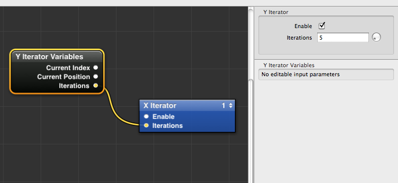


We have our patches in place, but how do we send the Iterator Variables output to the Sprite patch inputs? If you remember, we connected the Current Position value to the Interpolator patch to iterate the sprite along the X axis.
 To do the same along the Y axis, we need to repeat this operation, but we need to feed it with a new set of values, this time corresponding to the Y axis. 
However, the original Sprite and Interpolation patches are contained inside the X iterator macro, and there doesn’t seem to be a way for it to receive the new set of values coming from the Y Iterator Variables. You can see that the only input in the X iterator is the one that corresponds to the number of Iterations.


We double-click to open the X iterator macro, and see its contents. We have the original variables, the Interpolator and the Sprite. 
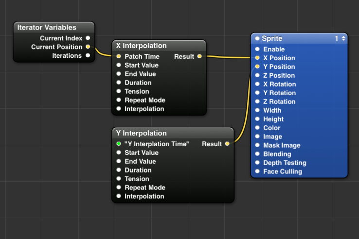
First, we need to create a new instance of the Interpolation patch to feed values to the Y Position of the Sprite. We do this either by copy-pasting the patch, or by selecting it and pressing command-d (cmd-D) to duplicate the patch. Now we should have two instances of the Interpolator.


However, we still need to communicate with the upper layer of the composition. In order to do this, we need to publish some of the inputs of the Interpolation patch. When we publish inputs or outputs, they are transferred automatically to the layer directly above the patch, in out case the X Iterator Macro that contains the patches. We do this by right-clicking on the patch, selecting the “publish inputs” menu, and selecting  “patch time”
Now we are given the option to rename the input, which is useful if you need to publish a lot of inputs or outputs that have similar names. Since we have multiple interpolators in this project, we will rename it “Y Interpolation Time”. This is simply an arbitrary name I have chosen, but obviously it can be anything you want. 


We press enter to confirm, and now we see that the the input has been renamed, and is coloured green. This indicates that the input has been published to the upper layer. If we navigate back to the view inside the Y iterator macro, we can see that the X iterator macro contains a new input, corresponding to our renamed Patch Time input from the interpolator below.


Now all we have to do is repeat what we did in the previous tutorial, and connect the Current Position output value from the Iterator Variables patch to the new input we created. This will send the information straight below to the Y position Interpolation patch.


We then open the X Iterator macro and connect the output value for the second Interpolator to the Y position input of the Sprite patch. As you can see, we now have a full grid of Squares positioned along X and Y, for a total of 25 squares. 


Of course we can change the number of squares per axis and play around with the inputs, but before there are a few steps we can take to “polish” the composition a bit. These steps might seem trivial for such a simple composition, but they come in handy when you have a large number of patches and layers.

First, we should learn about Input Splitters. These are accessed the same way we publish inputs, by right-clicking on the patch and selecting “input splitters”. When we select a value to split, we create a small node connected to the patch input representing that value, whatever the value is. We can rename it, change the value, but most importantly we can now easily share the value between multiple inputs, meaning that when we change that value, all the inputs are updated so that we don’t have to change each one manually all the time.


As an example, we can consider the Width and Height settings of the Sprite Patch. In our case the sprite represents a square, so the two values are always the same. But every time we need to change the size of the square, we need to repeat the operation twice. So we create a splitter for the Width value, rename it to “sprite size” and connect the output to both the width and height setting. Now we have a single value to control both inputs!


We can use the same process to share values between the two interpolators, so that we can edit the values easily, since our squares are supposed to be on an ordered grid.


Now that we have a set of values that control the size and placement of our squares, it can be useful to publish all out inputs to the top layer. This will save us the need to dive into the heart of the composition every time we decide to change a value. We simply right-click on each splitter and publish the values to the upper layer. By repeating the process on every layer of the composition, we end up with a top level macro with lots of inputs that control the patches at the heart of the composition.


 Finally, we can publish even this top-level set of inputs one more time, but where do they go? The answer is, in the viewer. 


This is a really clever option in Quartz Composer, and it means that you can run the composition in full screen from the viewer, and still have access to your input values allowing you to play with the settings and see the results right away. To access the settings, simply click on the Input Parameters button in the viewer, or click cmd-t with the viewer selected. 


We have seen how to use the iterator, and we have placed an Iterator inside another Iterator to create a grid of squares. 
So far the results of the tutorial are functional but don't look very fancy, so next time we will see how to assign separate values such as colours and rotation to each square in the grid. I hope this tutorial was helpful to you.


Other Tutorials:

-Part 3


(Leave a comment here to request new tutorials)

16 April, 2011

Quartz Composer Voxel Terrain Test 2

I've been trying to push my voxel composition a bit further. I noticed that switching from 64bit to 32bit QC shaves 2 seconds off the rendering time. No idea why, isn't 64bit-everything supposed to be faster?

I've also been adding color to the voxels. I've been using sprites exclusively instead of cubes to save on processing time. Color is dependent on the height of the voxel. I also used a gradient map to add terrain-like color mapping to the composition. Unfortunately this adds a lot to the rendering time, so instead of a good 5 seconds I now get 11 seconds.

-Interpolation:

This batch still uses two interpolation patches for the height values, useful if you like repeating patterns.


-Noise:

After using interpolators for a while, I tried switching to the Noise patch for the height values. I added multiple octaves to the noise input, in order to get different results. This is quite pleasant and more what I was aiming for, since now it looks a bit more controlled and landscape-like.

The downside of using color height maps is the performance hit. The two-color examples use a grid of max 256x256 iterations (128x128 gets very similar results though), but for the multi color ones I have to stop at 64x64.
Using 128x128 seems to crash or freeze Quartz Composer. Still good for pixel art I guess :-)


09 April, 2011

Outcast GDC Paper


Outcast is a PC game that came out in around 2000. While I haven’t played the game, it gets mentioned often in  discussions on Voxel graphics because it used the technique for its terrain rendering. Specifically, there is a presentation the creators gave at GDC in 2000 which is supposed to be floating around the net in the form of a paper. It discussed the techniques used for the game is some detail. 

The company however went bust ages ago and the link most papers refer to is dead. Luckily I was able to locate the material the other day on some website, albeit in the form html pages. They only exist on the server file list however, so you’ll have to visit each page individually.

Here is the link to the hosted pages, you will have to click on the html pages in order to read them. If you’re interested, I suggest you save them before they disappear again!

08 April, 2011

TUTORIAL: Iterators in Quartz Composer - Part 1


Quartz Composer is an ideal tool for artists because it allows one to make small visual-oriented programs, without the need to learn computer code. Instead it relies on nodes and macros patches. 

Nodes are controlled by inserting the values straight in an input field in the node or by connecting the output of one node (say a math equation) to the input of another node (like the width of a square).
A  Macro is like a box that contains nodes or other macros. It can be used to modify the behaviour or output of the patches inside it or, much like a real box, simply to contain the patches without affecting them in order to clean up the editor space.


This tutorial focuses on the use of Macros, and in particular the one called “Iterator”. I like to think of this as a sort of “magic box” capable of creating multiple instances of a base object. Furthermore, each instance can have its own properties, rather than just inheriting the properties of the original object. 

To get started, we drag a Sprite patch into the editor. This displays a basic square object. We can control the size, placement, color and rotation of the square. We can also assign an image to be displayed in the square.


We give the Sprite a Width and Height of 0.2 to make it smaller, and place it on the upper left side of the Viewer, with X= -0.7  and Y= 0.7
(Note that for the purposes of this tutorial, I set the ratio of the viewer to a fixed value so it’s always square, rather than being freeform. I can resize the viewer, but the rendering area will always have the same height and width ratio).


Now that we have our Sprite ready, we select an Iterator macro patch, and copy-paste our Sprite patch inside it. We can delete the original. Our Sprite is now inside the Iterator, and the Macro tells us we have 10 instances of the sprite. Despite this, nothing seems to happen, and the sprite is still where we left it. 


The next step is to introduce another patch in our composition called Iterator Variables. This patch is very important as it works in tandem with the Iterator. it has to be placed inside the Iterator macro  in order to work, on the same level as the object you want to affect, in this case our Sprite.


We place the Iterator Variables patch inside the macro, and we see no inputs, and 3 outputs. The first is Current Index: this corresponds to the index of all the object instances created, and assigns a number to it. It will output a max amount of numbers (0,1,2,3,4,...) depending on the number of instances. Note that these are not idle numbers, but correspond to each instance of the object.
Next is Current Position. This will output numbers corresponding to each instance as before, but only from 0 to 1. 
Third is Iterations, which outputs the number of iterations produced by the iterator. This corresponds to how many copies we’re making.

Now, let’s assume we want to make 5 copies of our sprite, and we want them to go horizontally from one end of the rendering area to the other. Our sprite is now on the upper left side of the rendering area, corresponding to (X=-07, Y=0.7). Since we want to create one row of sprites, we only need to influence the X value of the Sprite. The Y value will stay the same. The start value for X is -0.7, corresponding to the left side of the rendering area. We want the last Sprite to have an X value of 0.7 ( the right side), and we want to have 5 instances in total. 

For the next step, we’re going to introduce another extremely useful patch, called Interpolation. This is an animation patch, meaning it does what it does according to a timeline which starts as soon as we run our composition, and stops when the operation is concluded (assuming we haven’t set it on a loop, in which case it will repeat the operation over and over).


We drag the Interpolation patch inside the Iterator, because we need it to interact with both the Sprite patch and the all-important Iterator Variables. In our case, we need it to provide our sprites with a value for their X position. This value needs to be unique for each instance of the Sprite, and we want it to begin at -0.7, and end at 0.7. 
This, by the way , is what the interpolator does. In interpolates continuously between a start value and an end value. It does so according to a timeline, and it also does it according to a set duration, meaning how long it will take for it to go from the start value to the end value. For instance, we could set it to go from 0 to 2 in the course of 60 seconds, or however long we wish. 
There are more input settings on the Interpolator patch, such a tension (holds back or pushes forward the interpolation curve) , repeat mode (allows to loop the animation) and interpolation (selects different interpolations curves). 

For of our project, we will have to place the Interpolation patch on a different timeline. This is a bit of a hidden setting in QC, but every animation patch that relies on a timeline can actually be set to also operate on an external or separate timeline. This means that instead of having the interpolator start automatically as soon as we run the composition, and ending only when we stop it, we can set the interpolator to start whenever we please according to the values we decide to use. 


Looking around the editor, the only other patch that can immediately provide any input to the interpolator is the Iterator Variables patch. We right-click on top of the Interpolation patch, where the patch name is, and we are presented with a few options. We select option number 3, and now our interpolator has a brand new input field, called patch time. This is how we control the patch animation according to our needs. 
Going back to our iterator variables, we look at Current Position: as I mentioned before, this gives us a unique number from 0 to 1 for every instance we create. In our Iterator macro patch, we change the number of iterations from the default 10 to 5. 


In the Interpolator patch, we set the values of start value and end value to -0.7 and 0.7 respectively. We then connect the Current Position output to the Patch Time input of the interpolator. We set the Repeat Mode of the Interpolation path to “none”, meaning the action will not loop on itself. Finally, we change the Duration of the interpolation to 1.
What we have  done here is we have given the interpolator a different moment in the timeline for each instance of the sprite, so that each sprite has a set, clean value between -0.7 and 0.7 on the X axis. The duration of the interpolation equals the max value that is passed on from the Current Position output (1), so the different sprites are like snapshots of the different stages of the animation frozen in time.


We now pass the output value of the Interpolation patch to the X value input Sprite patch, and we can see that we have 5 squares in our render area, each in its own place. 


You can play around with the number of iterations, and no matter how many sprites, they will always be ordered and placed. A large number of sprites will eventually blend into each other, so try to play around with the sprite size as well.


You can see why earlier I referred to the Iterator macro as a a sort of “magic box”. With very little manual work , we are able to produce endless copies of an object. This allows the artist not only to save time, but also to think of a composition in a completely abstract way. I personally find it an hugely empowering tool, and one that opens several creative avenues. 

In this tutorial I gave a very basic example of the power of Quartz Composer, I hope it can be helpful to someone! I’ll make sure to follow it with some more tutorials in the future, as there seems to be a distinct lack of these on the web.

Next Tutorials:


-Part 2
-Part 3

(Leave a comment here to request new tutorials)

06 April, 2011

Quartz Composer Voxel Terrain Test

A small "landscape" to test performance of voxel for a terrain project. The main test field is composed of cubes that have been iterated on a grid 300 times. That adds up to 90000(!) instances. Rendering time in Quartz Composer is about 7 seconds. Switching to a simple sprite instead of 3d cubes shaves off about 2 seconds to the rendering time.

The shape of the landscape is directed by an iterator, different interpolation methods result in different shapes. Additional complexity can be obtained by linking some of the parameters of the interpolator to another interpolator.