Analytics

Showing posts with label Mesh. Show all posts

28 May, 2012

TUTORIAL: 3D Mesh Construction in Quartz Composer - Part 2


- Part 1


In the previous tutorial we used structures to construct a polygon mesh in the shape of a triangle. Now it’s time to add some colour to our vertices. This information needs to be presented to the Mesh Creator patch in much the same way as the vertex one. First though we will be converting our triangle to a square. In order to do this we will simply be adding one more vertex to our structure and changing the existing values to reflect the new shape. 

First change the number of inputs in the "Vertices" structure maker form 3 to 4, then we duplicate one of our existing vertex structures. When constructing a quad in OpenGl the vertex order is important, especially for later on when we will be adding texture coordinates. In this case it needs to begin from the Bottom Left Vertex, on to the Top Left, Bottom Right and ending on the Top Right.  

The unconventional running order is due to the fact that when we are still building a set of triangles (instead of an actual quad) using an OpenGL Triangle Strip. This means we have two triangles on top of each other, but using the triangle strip allows to do this with only 4 vertices instead of 6. For a more detailed explanation follow the liked article.

1 - Bottom Left: X = -0.5, Y = -0.5 , Z = 0

2 - Top Left: X = −0.5, Y = 0.5, Z = 0

3 - Bottom Right: X = 0.5, Y = -0.5, Z = 0

4 = Top Right: X = 0.5, Y = 0.5, Z = 0


Our viewer now displays a square instead of a triangle. Since we will be adding new structures, it’s a good idea at this stage to clean up our workspace a bit. To do this we select all the patches related to the vertices and hit the “Create Macro” button at the top. Our patches are now neatly held in a small macro container that we rename “Vertices”. 


Next are the color structures. To begin, we duplicate out “Vertices” macro and rename it “Colors”. Since Color information requires four values (RGBA) we need to update our individual structure maker patches to have 4 inputs, and rename the input splitters as well

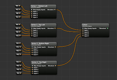


Now we could at this point enter each colour value manually, but that would be a pain. Instead we drag in a "Color To RGB" patch that allows us to choose a color from the color picker and output its individual RGBA values. 


With this done we can now choose 4 different colors and assign them to each vertex. To make it so that we don’t have to open the macro each time we want to try new colors, we can publish the colour input of each Color To RGB patch so that they appear outside the macro in the main view. Connect the Colors structure output to the input in the Mesh Creator patch and we now have a Quad with coloured vertices!


Next up are texture coordinates. You won’t be surprised to learn this will be yet another structure. We take our existing structure and change the input number to 2. The splitters will be named X and Y. Rather than the actual position values, X and Y will oscillate between 0 and 1:

1 - Bottom Left: X = 0, Y = 0 

2 - Top Left: X = 0, Y = 1

3 - Bottom Right: X = 1, Y = 0

4 = Top Right: X = 1, Y = 1


Our mesh is now ready to display image textures! To do this simply connect any image to the “Texture” input in the Mesh Creator Patch. Note that to display an image with its original colors you will have to set every vertex color to be white, otherwise the image displayed will be appear tinted!

Next up, actual 3-dimensional objects and Normals!

27 May, 2012

TUTORIAL: 3D Mesh Construction in Quartz Composer - Part 1


This tutorial will outline basic use of the Mesh Creator patch and the Mesh  Renderer patch in Quartz Composer, in addition to the Kineme Structure Maker patch.

The fundamental thing to understand about creating 3D meshes in QC is that the application in this regard is a basic front for common OpenGL functions. Therefore, to gain a basic understanding of how these things work we can first consult any tutorial on OpenGl basics, then find a way to apply it to QC. 
A good resource for this is the series of tutorials by NeHE productions .

We will create a basic polygon, and assign colour and texture coordinates to it so that we can change its appearance and display images on its surface.

To begin, we drag in the Mesh Creator patch. This patch is responsible for taking in all the data required to create a polygon and creating a mesh from it. The mesh will then be displayed by the Mesh Renderer patch.


A polygon is, at its most basic, a series of vertices. Each vertex is in turn a point in space, determined by its XYZ position. In order to create a polygon we will therefore need to first specify the XYZ  coordinates of a vertex, repeat the process for the amount of vertices required to determine the shape chosen, then feed this to the Mesh Creator and then to the Mesh Renderer.

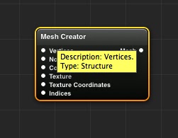
What kind of input does the Mesh Renderer take? To determine this we hover with the mouse over the "Vertices" input slot, and see that the type is Structure.

We have dealt with structures in a previous tutorial . This time however we are not just reading a structure, we are creating one. To do this, we require and external patch by the good people at Kineme called Structure Maker. The patch is part of the “Kineme Data Tools” plugin set and is found here.


This patch will enable us to determine a series of inputs and make a structure out of them. To build our polygon we will begin by setting the vertex list. We rename the Structure Maker patch to “Vertices”.

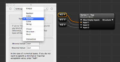
For this tutorial we will create a triangle, so we will need a total of 3 vertices as inputs. In order to prepare the Structure Maker patch, we need to change the number of inputs from the default 1 to 3. We do this by selecting the “Parameters” panels for the patch, navigating to the “Settings” tab and changing the number to 3.


Now that the Vertices Structure Maker is ready, we need to create the individual vertices. As each vertex is determined by 3 values ( XYZ ) we will need to create a structure for each. As we already have a SM patch ready, we duplicate it and rename it to “Vertex 1 - Top”. This will contain the coordinates for the top vertex of the triangle. We also create input splitters for each vertex, remembering to change the input type from “Virtual” to “Number”.


The coordiantes for our "Top" vertex will be:  X = 0 , Y = 0.5 , Z = 0 . This will place the top vertex in the centre horizontally but above the centre vertically.

Now all that is left is to repeat the process by simply duplicating the setup for the other two vertices and changing the values to create a triangle shape:

  - TopX = 0 , Y = 0.5 , Z = 0
  - Bottom LeftX = −0.5 , Y = −0.5 ,  Z = 0
  - Bottom RightX = 0.5 , Y = -0.5 ,  Z = 0


We then simply connect the Mesh Creator output to the “Mesh” input of the Mesh Renderer patch… et voilĂ ! We have our very own triangle mesh created entirely in Quartz Composer. 


As you have probably noticed, there are a few more inputs in the Mesh Creator patch. We will be dealing with those in future parts of the tutorial. In the meantime feel free to play with the values of the vertices and perhaps move them around in space. 
Notice that even though we have obtained a 2D image of a triangle, the mesh is actually a 3D object able to move around in space, meaning we are not restricted to simple triangles but we can create potentially any shape. That triangle however is the foundation of all 3D models. I hope you have enjoyed this tutorial and make sure to keep an eye open for the next instalments.

Part 2


30 May, 2011

Quartz Composer Procedural Terrain Mesh Test

The terrain mesh is generated by creating vertex structures with iterators and feeding it to the Kineme GL Triangle Structure patch. I initially tried with the built in Mesh Creator patch, but this one seems faster and more stable. 

The current method is not incredibly fast as it uses individual quads rather than long triangle strips. A 64*64 grid takes 17 seconds! I have a version which is faster that uses iterated triangle strips, but I’m having some problems wrapping the end of the mesh so I need to clean it up further. A lot of the slow-down is due to the way I calculate vertex colors I think.

The height values are generated by a Noise patch and entirely mediated by math to get the “island” effect, with the terrain coming down at the edges into flat land. No heightfield images are used.
Normals are not yet calculated so no shadows for now. The vertex colors are generated through the Color Map patch fed by gradients and an initial colouring of the vertices from black to white based on the height value. 

Overall quite primitive and unpolished, but I look forward to refining it.


These are earlier versions using the built-in Mesh Creator patch. The slight advantage of this is that you can use the Grid Normals Generator patch to generate normals and get shadows, however this proved very unstable so I’ll probably have to find an alternative way.