
In the previous tutorial on iterators I showed how to create a simple row of sprites along the X axis. Now we will take that example further, and create a full grid of squares.
The way we do this is by creating multiple copies of the previous iterator macro by putting that macro patch inside another iterator. Right now in our editor we can see the previous iterator on its own (apart from the Clear patch). Because labels are important, we should rename the current iterator by double-clicking on the patch name and inserting a new name, in this case” X Iterator”. While this is not strictly necessary, it helps us distinguish it from the other patches, and is especially helpful if we have a very complex project.

Next to our X Iterator we create a new Iterator Macro and rename it “Y Iterator”. We copy-paste the X-Iterator inside the Y Iterator macro and get rid of the original, and in the Y iterator we change iterations value to 5 to match the X Iterator.
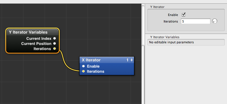
Now in our top editor view we only have the Y Iterator and the Clear patch. When we double click inside the Y Iterator to view its contents we find the X iterator. Just like with the previous tutorial, we need to place an Iterator Variables patch inside the Y Iterator Macro, next to the X Iterator.
To make sure that the number of iterations are the same for each axis, we connect the output of the Iterations value to the input of the Iterations value of the X Iterator macro. This way, we only need to change the number of iterations of one macro to change both.
We have our patches in place, but how do we send the Iterator Variables output to the Sprite patch inputs? If you remember, we connected the Current Position value to the Interpolator patch to iterate the sprite along the X axis.
To do the same along the Y axis, we need to repeat this operation, but we need to feed it with a new set of values, this time corresponding to the Y axis.
However, the original Sprite and Interpolation patches are contained inside the X iterator macro, and there doesn’t seem to be a way for it to receive the new set of values coming from the Y Iterator Variables. You can see that the only input in the X iterator is the one that corresponds to the number of Iterations.

We double-click to open the X iterator macro, and see its contents. We have the original variables, the Interpolator and the Sprite.
First, we need to create a new instance of the Interpolation patch to feed values to the Y Position of the Sprite. We do this either by copy-pasting the patch, or by selecting it and pressing command-d (cmd-D) to duplicate the patch. Now we should have two instances of the Interpolator.

However, we still need to communicate with the upper layer of the composition. In order to do this, we need to publish some of the inputs of the Interpolation patch. When we publish inputs or outputs, they are transferred automatically to the layer directly above the patch, in out case the X Iterator Macro that contains the patches. We do this by right-clicking on the patch, selecting the “publish inputs” menu, and selecting “patch time”.
Now we are given the option to rename the input, which is useful if you need to publish a lot of inputs or outputs that have similar names. Since we have multiple interpolators in this project, we will rename it “Y Interpolation Time”. This is simply an arbitrary name I have chosen, but obviously it can be anything you want.

We press enter to confirm, and now we see that the the input has been renamed, and is coloured green. This indicates that the input has been published to the upper layer. If we navigate back to the view inside the Y iterator macro, we can see that the X iterator macro contains a new input, corresponding to our renamed Patch Time input from the interpolator below.

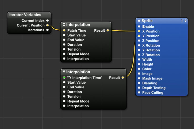
Now all we have to do is repeat what we did in the previous tutorial, and connect the Current Position output value from the Iterator Variables patch to the new input we created. This will send the information straight below to the Y position Interpolation patch.

We then open the X Iterator macro and connect the output value for the second Interpolator to the Y position input of the Sprite patch. As you can see, we now have a full grid of Squares positioned along X and Y, for a total of 25 squares.

Of course we can change the number of squares per axis and play around with the inputs, but before there are a few steps we can take to “polish” the composition a bit. These steps might seem trivial for such a simple composition, but they come in handy when you have a large number of patches and layers.
First, we should learn about Input Splitters. These are accessed the same way we publish inputs, by right-clicking on the patch and selecting “input splitters”. When we select a value to split, we create a small node connected to the patch input representing that value, whatever the value is. We can rename it, change the value, but most importantly we can now easily share the value between multiple inputs, meaning that when we change that value, all the inputs are updated so that we don’t have to change each one manually all the time.
As an example, we can consider the Width and Height settings of the Sprite Patch. In our case the sprite represents a square, so the two values are always the same. But every time we need to change the size of the square, we need to repeat the operation twice. So we create a splitter for the Width value, rename it to “sprite size” and connect the output to both the width and height setting. Now we have a single value to control both inputs!
We can use the same process to share values between the two interpolators, so that we can edit the values easily, since our squares are supposed to be on an ordered grid.

Now that we have a set of values that control the size and placement of our squares, it can be useful to publish all out inputs to the top layer. This will save us the need to dive into the heart of the composition every time we decide to change a value. We simply right-click on each splitter and publish the values to the upper layer. By repeating the process on every layer of the composition, we end up with a top level macro with lots of inputs that control the patches at the heart of the composition.


Finally, we can publish even this top-level set of inputs one more time, but where do they go? The answer is, in the viewer.

This is a really clever option in Quartz Composer, and it means that you can run the composition in full screen from the viewer, and still have access to your input values allowing you to play with the settings and see the results right away. To access the settings, simply click on the Input Parameters button in the viewer, or click cmd-t with the viewer selected.
We have seen how to use the iterator, and we have placed an Iterator inside another Iterator to create a grid of squares.
So far the results of the tutorial are functional but don't look very fancy, so next time we will see how to assign separate values such as colours and rotation to each square in the grid. I hope this tutorial was helpful to you.