- Part 1
In the previous tutorial we used structures to construct a polygon mesh in the shape of a triangle. Now it’s time to add some colour to our vertices. This information needs to be presented to the Mesh Creator patch in much the same way as the vertex one. First though we will be converting our triangle to a square. In order to do this we will simply be adding one more vertex to our structure and changing the existing values to reflect the new shape.
First change the number of inputs in the "Vertices" structure maker form 3 to 4, then we duplicate one of our existing vertex structures. When constructing a quad in OpenGl the vertex order is important, especially for later on when we will be adding texture coordinates. In this case it needs to begin from the Bottom Left Vertex, on to the Top Left, Bottom Right and ending on the Top Right.
The unconventional running order is due to the fact that when we are still building a set of triangles (instead of an actual quad) using an OpenGL Triangle Strip. This means we have two triangles on top of each other, but using the triangle strip allows to do this with only 4 vertices instead of 6. For a more detailed explanation follow the liked article.
1 - Bottom Left: X = -0.5, Y = -0.5 , Z = 0
2 - Top Left: X = −0.5, Y = 0.5, Z = 0
3 - Bottom Right: X = 0.5, Y = -0.5, Z = 0
4 = Top Right: X = 0.5, Y = 0.5, Z = 0
Our viewer now displays a square instead of a triangle. Since we will be adding new structures, it’s a good idea at this stage to clean up our workspace a bit. To do this we select all the patches related to the vertices and hit the “Create Macro” button at the top. Our patches are now neatly held in a small macro container that we rename “Vertices”.
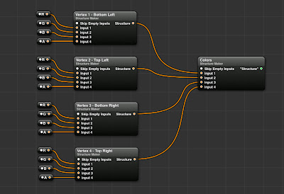
Next are the color structures. To begin, we duplicate out “Vertices” macro and rename it “Colors”. Since Color information requires four values (RGBA) we need to update our individual structure maker patches to have 4 inputs, and rename the input splitters as well
Now we could at this point enter each colour value manually, but that would be a pain. Instead we drag in a "Color To RGB" patch that allows us to choose a color from the color picker and output its individual RGBA values.
With this done we can now choose 4 different colors and assign them to each vertex. To make it so that we don’t have to open the macro each time we want to try new colors, we can publish the colour input of each Color To RGB patch so that they appear outside the macro in the main view. Connect the Colors structure output to the input in the Mesh Creator patch and we now have a Quad with coloured vertices!
Next up are texture coordinates. You won’t be surprised to learn this will be yet another structure. We take our existing structure and change the input number to 2. The splitters will be named X and Y. Rather than the actual position values, X and Y will oscillate between 0 and 1:
1 - Bottom Left: X = 0, Y = 0
2 - Top Left: X = 0, Y = 1
3 - Bottom Right: X = 1, Y = 0
4 = Top Right: X = 1, Y = 1
Our mesh is now ready to display image textures! To do this simply connect any image to the “Texture” input in the Mesh Creator Patch. Note that to display an image with its original colors you will have to set every vertex color to be white, otherwise the image displayed will be appear tinted!
Next up, actual 3-dimensional objects and Normals!


