Analytics

Showing posts with label Tutorial. Show all posts

28 May, 2012

TUTORIAL: 3D Mesh Construction in Quartz Composer - Part 2


- Part 1


In the previous tutorial we used structures to construct a polygon mesh in the shape of a triangle. Now it’s time to add some colour to our vertices. This information needs to be presented to the Mesh Creator patch in much the same way as the vertex one. First though we will be converting our triangle to a square. In order to do this we will simply be adding one more vertex to our structure and changing the existing values to reflect the new shape. 

First change the number of inputs in the "Vertices" structure maker form 3 to 4, then we duplicate one of our existing vertex structures. When constructing a quad in OpenGl the vertex order is important, especially for later on when we will be adding texture coordinates. In this case it needs to begin from the Bottom Left Vertex, on to the Top Left, Bottom Right and ending on the Top Right.  

The unconventional running order is due to the fact that when we are still building a set of triangles (instead of an actual quad) using an OpenGL Triangle Strip. This means we have two triangles on top of each other, but using the triangle strip allows to do this with only 4 vertices instead of 6. For a more detailed explanation follow the liked article.

1 - Bottom Left: X = -0.5, Y = -0.5 , Z = 0

2 - Top Left: X = −0.5, Y = 0.5, Z = 0

3 - Bottom Right: X = 0.5, Y = -0.5, Z = 0

4 = Top Right: X = 0.5, Y = 0.5, Z = 0


Our viewer now displays a square instead of a triangle. Since we will be adding new structures, it’s a good idea at this stage to clean up our workspace a bit. To do this we select all the patches related to the vertices and hit the “Create Macro” button at the top. Our patches are now neatly held in a small macro container that we rename “Vertices”. 


Next are the color structures. To begin, we duplicate out “Vertices” macro and rename it “Colors”. Since Color information requires four values (RGBA) we need to update our individual structure maker patches to have 4 inputs, and rename the input splitters as well

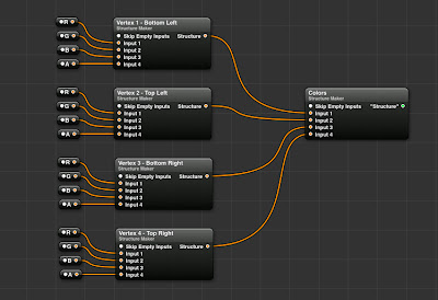


Now we could at this point enter each colour value manually, but that would be a pain. Instead we drag in a "Color To RGB" patch that allows us to choose a color from the color picker and output its individual RGBA values. 


With this done we can now choose 4 different colors and assign them to each vertex. To make it so that we don’t have to open the macro each time we want to try new colors, we can publish the colour input of each Color To RGB patch so that they appear outside the macro in the main view. Connect the Colors structure output to the input in the Mesh Creator patch and we now have a Quad with coloured vertices!


Next up are texture coordinates. You won’t be surprised to learn this will be yet another structure. We take our existing structure and change the input number to 2. The splitters will be named X and Y. Rather than the actual position values, X and Y will oscillate between 0 and 1:

1 - Bottom Left: X = 0, Y = 0 

2 - Top Left: X = 0, Y = 1

3 - Bottom Right: X = 1, Y = 0

4 = Top Right: X = 1, Y = 1


Our mesh is now ready to display image textures! To do this simply connect any image to the “Texture” input in the Mesh Creator Patch. Note that to display an image with its original colors you will have to set every vertex color to be white, otherwise the image displayed will be appear tinted!

Next up, actual 3-dimensional objects and Normals!

27 May, 2012

TUTORIAL: 3D Mesh Construction in Quartz Composer - Part 1


This tutorial will outline basic use of the Mesh Creator patch and the Mesh  Renderer patch in Quartz Composer, in addition to the Kineme Structure Maker patch.

The fundamental thing to understand about creating 3D meshes in QC is that the application in this regard is a basic front for common OpenGL functions. Therefore, to gain a basic understanding of how these things work we can first consult any tutorial on OpenGl basics, then find a way to apply it to QC. 
A good resource for this is the series of tutorials by NeHE productions .

We will create a basic polygon, and assign colour and texture coordinates to it so that we can change its appearance and display images on its surface.

To begin, we drag in the Mesh Creator patch. This patch is responsible for taking in all the data required to create a polygon and creating a mesh from it. The mesh will then be displayed by the Mesh Renderer patch.


A polygon is, at its most basic, a series of vertices. Each vertex is in turn a point in space, determined by its XYZ position. In order to create a polygon we will therefore need to first specify the XYZ  coordinates of a vertex, repeat the process for the amount of vertices required to determine the shape chosen, then feed this to the Mesh Creator and then to the Mesh Renderer.

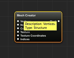
What kind of input does the Mesh Renderer take? To determine this we hover with the mouse over the "Vertices" input slot, and see that the type is Structure.

We have dealt with structures in a previous tutorial . This time however we are not just reading a structure, we are creating one. To do this, we require and external patch by the good people at Kineme called Structure Maker. The patch is part of the “Kineme Data Tools” plugin set and is found here.


This patch will enable us to determine a series of inputs and make a structure out of them. To build our polygon we will begin by setting the vertex list. We rename the Structure Maker patch to “Vertices”.

For this tutorial we will create a triangle, so we will need a total of 3 vertices as inputs. In order to prepare the Structure Maker patch, we need to change the number of inputs from the default 1 to 3. We do this by selecting the “Parameters” panels for the patch, navigating to the “Settings” tab and changing the number to 3.


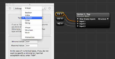
Now that the Vertices Structure Maker is ready, we need to create the individual vertices. As each vertex is determined by 3 values ( XYZ ) we will need to create a structure for each. As we already have a SM patch ready, we duplicate it and rename it to “Vertex 1 - Top”. This will contain the coordinates for the top vertex of the triangle. We also create input splitters for each vertex, remembering to change the input type from “Virtual” to “Number”.


The coordiantes for our "Top" vertex will be:  X = 0 , Y = 0.5 , Z = 0 . This will place the top vertex in the centre horizontally but above the centre vertically.

Now all that is left is to repeat the process by simply duplicating the setup for the other two vertices and changing the values to create a triangle shape:

  - TopX = 0 , Y = 0.5 , Z = 0
  - Bottom LeftX = −0.5 , Y = −0.5 ,  Z = 0
  - Bottom RightX = 0.5 , Y = -0.5 ,  Z = 0


We then simply connect the Mesh Creator output to the “Mesh” input of the Mesh Renderer patch… et voilĂ ! We have our very own triangle mesh created entirely in Quartz Composer. 


As you have probably noticed, there are a few more inputs in the Mesh Creator patch. We will be dealing with those in future parts of the tutorial. In the meantime feel free to play with the values of the vertices and perhaps move them around in space. 
Notice that even though we have obtained a 2D image of a triangle, the mesh is actually a 3D object able to move around in space, meaning we are not restricted to simple triangles but we can create potentially any shape. That triangle however is the foundation of all 3D models. I hope you have enjoyed this tutorial and make sure to keep an eye open for the next instalments.

Part 2


13 May, 2011

TUTORIAL: Structures and Index Members in Quartz Composer


This tutorial will outline basic use of Structures and the Index Member patch in Quartz Composer.

A structure is simply a way of organising data. It can be thought of as a series of labeled folders containing files, like a folder with pictures of your summer vacation that contains subfolders organised by date.

Even though we might not notice it, in Quartz Composer we deal with structures in many ways: any time we load something from a folder, when we create groups of values dynamically with Iterators, when building a 3d mesh etc.
It’s probably easier to just show you, so in this tutorial we will outline a simple way of displaying RSS feeds in Quartz Composer.

We begin by loading a patch called RSS Importer.  As the name implies, this takes an internet RSS feed and downloads the contents much like any other reader does.


This patch receives as input the feed URL and an “update signal” boolean. It outputs the feed information and the articles, plus the download progress and a quick pulse signal when the download is done.

The output of this patch is where we start dealing with structures. Rather than giving us a huge block of text, the output will be structured the same way as when we read it on the website (title, date, content, author etc.). 
The article list will be a structure, and each article will itself be a structure made of the individual elements of the article.

In order to view the contents we need a way to display the text. We do this by loading the Image with String patch. This is an extremely useful patch that allows us to display text in Quartz Composer as an image. We can change the font, alignment, size etc. 
We drag in a Sprite patch to display the output of the Image with String patch.


As a test, we can try to connect the “Article List” output to the “String” input of the Image with String patch, and the “Image” output from there to the Sprite "Image" input. All we get is a pretty blurry <QCStructure> bit of text. 
This is because no actual text is loaded, and the Image with String is just passing the output type information. So the RSS patch is outputting a structure, and we need to separate the individual elements of the structure to pass it to the IWS (Image with String) patch. 


Before we do anything else, let’s clean up the image output of the patches so that it’s readable. We select the settings tab for the IWS patch, and change the dimensions from "Fixed" to "Dynamic". This will allow us to deal in pixels rather than units. 


Next we connect the “Display Width” and “Display Height” outputs from the IWS patch to the "Width" and "Height" inputs of the Sprite patch.


The text is now clearer but still small, so we change the “Font Size” input in the IWS patch to 20. The text is now big and readable.


We’re still seeing the old bit of text, so let’s get to the article data. As we said, the RSS importer outputs structures, and we need to separate the various elements in order to display them.
To separate the elements we make use of the Structure Index Member patch. 
This patch takes in a structure and only selects the member of the structure we need from the index.


We need to connect the Article List output from the RSS patch to the Structure input of the SIM (Structure Index Member) patch. We then connect its Member output to the String input of the IWS patch.


Despite doing this, we’re still displaying the same text. To check what the RSS patch is actually sending out, we can hover with our mouse pointer over the Article List output connector.


As you can see, this lets us view the actual contents of the feed and understand how the structure is organised. We can see the number of elements in the structure and the contents of the sub-structures. This will help us decide how to use the SIM patch.
As an example, let’s say that we want to display the text from my recent blogpost. We need to extract the first element in the list from the main article structure (0), and then we need the article description, indexed at (1) in the sub-structure.

First we select Index 0 in the SIM patch. We rename this patch to “Article List”.


We now need a second SIM patch, in order to extract the specific element we need from the first structure. We create a new one and rename it “Article Description”. We connect the "Member" output of the first SIM to the "Structure" input of the second SIM, and connect the output of this one to the "String" input of the IWS patch.


If we look at our viewer, we are now displaying the Title of the articles. This is because the second SIM patch is still set on index member (0). When we change the index to (1), we finally get the text we needed.


The text however is being displayed in a long horizontal line. This is because we haven’t specified the dimensions of the image that is being passed from the IWS patch to the Sprite. To do this, we need the Rendering Destination Dimensions patch. This patch contains all the information about the dimensions of our viewer destination, and can be used to resize images so that they fit the final rendering area.


In our case, we are going to feed the info to the IWS patch, since it’s the one generating the image. We’re dealing in pixels, so we connect the “Pixels Wide” and “Pixels High” outputs from to the Rendering Destination Dimensions patch to the “Image Width” and “Image Height” inputs of the IWS.


As you can see,the text is now displayed correctly within the viewer bounds and is clear and readable. This is a very basic use of this method, but with more time one could format it in a very attractive way with different fonts and colors for the various elements.

Hopefully this has provided a valid introduction to the use of Structures and Index Members in Quartz Composer. We have also seen how versatile a tool QC really is, as in no time we have created the foundation for a customised RSS reader that can be easily extended. 

(This tutorial was requested by reader "instrumentality". Leave a comment here to request new tutorials)

06 May, 2011

Tutorial Requests

As I'm seeing some traffic from Google searches regarding Quartz Composer tutorials, I'm interested in knowing if anyone has any specific requests for new tutorials covering QC. If you visit the blog, feel free to leave a comment on this post to suggest new content for the future and I'll be happy to cover it (provided it's within my grasp!).

24 April, 2011

TUTORIAL: Iterators In Quartz Composer - Part 3

Previous Tutorials:


Following the previous two tutorials, we now have an ordered grid of square sprites in our viewer. After making our squares all look the same, we will now add some variation to them.

First of all, we add color. In order to define a list of colors to choose from, we introduce the Multiplexer Patch. This is a very useful patch that simply presents a list of items ordered by index. The list can be as long as we want, and begins at 0. The list can contain colors, numbers, booleans, indexes, data structures, 3d meshes and images. Basically we can make a list of anything we want, choose one item from the list, and this item will be passed on to the output.

In our case, we need a list of colors. We navigate inside the x iterator where our sprite patch is and drag the multiplexer patch there.


In order to select the colors we want, we need to change the settings for the patch. We do this by selecting the multiplexer in out editor and then clicking on the display setting button in the toolbar.


When we do this, we see that the number of inputs is set to 2, and the input type is se to “Virtual”. This means that the multiplexer will accept anything that is connected to the inputs and simply pass is it along. However, we want to pass a specific type of input, so we select the input type drop-down menu and change it to “Color”. We also increase the number of inputs to 5.


We close the settings panel and we can now see our multiplexer sports 5 inputs. It has also been renamed to “Color Multiplexer”. The inspector will also show that the inputs are now all colors. 


Next we select the color inputs and choose a different color for each. With our colors in place, we connect the output of the color multiplexer to the “color” input of the sprite patch. When we select a color from the multiplexer index, that value is passed to all our sprites.


Now our sprites are colored, but what we really want is to assign a different color to each square. In order to do this, we are going to use a Random Patch. This patch generates a random value between a minimum and maximum value that we assign.


The random patch however is animated, and generates numbers continuously when we start the composition following the main timebase. We need the number to be static, and we also need each sprite to have a different number corresponding to the color index. 

First, we right click on the random patch and change the timebase to “external”, like we did in the previous tutorial. This ensures that the number generated will be static. Next, we need to assign a timebase to the patch. We do this by passing the Current Index output  from the Iterator Variables  patch to the timebase input of the random patch. Since we need both indexes from the two different iterators, we have to add them together. 

We add a bit of math to our composition by dragging a Math to the editor. This is used to perform all the basic math functions between two or more values. 


The math patch presents two inputs, and the values are being added. We can change the mathematical operation to anything we want by selecting it in the inspector tab. 
Now we need to connect the two Current Index outputs to the inputs of the math patch, and they will be added. To add the index for the Y iterator, we need to publish the second input of the math patch to the upper level. We can rename the input “Y Current Index” for clarity. The first input will correspond to the X Current Index. 


The multiplexer index only needs values up to 4 even if it has 5 inputs, because it starts from 0. We select the random patch and set the Min value to 0 and the Max value to 4. We then connect the output of the random patch to the index input value of the multiplexer. This will assign a different color to each square in our grid.


And there you have it! Random colors for each square. The values generated by the random patch are not terribly diverse, but we can increase the number of color inputs in the multiplexer patch as much as we want. Just remember that the changes need to the reflected in the maximum value of the random patch.
You can also play around with the Random patch settings tab and see what happens.

Now that we have assigned a different color to each square, we can repeat the process for any sprite attribute we like. For instance, rotation and size. We can assign a random patch to the “Z Rotation” input of the sprite and pass it a random value between 0 and 360. 


We can also do the same for the sprite size, and select different values for Width and Height.


You could also experiment by assigning a different image to each sprite.

And last, to display some interesting color overlap, we can change the blend value of the sprite patch to “add”. This will add the color of the overlapping sprites together when they meet. To make this work better, you should change the transparency of the colors to about 25% or less.


With that we wrap up this series of tutorials. Hopefully by now  you can (with some imagination) see the huge potential of the Iterator Macro, and what can be achieved very quickly by adding some randomness to the composition. Remember to experiment!


(Leave a comment here to request new tutorials)